Homelab Power Savings, Part 2: Power Measurement
So far, I’ve been using nothing but RAPL and my servers’ PMBus support to measure power usage. The problem is, this means I can’t measure the rest of my rack – only a couple servers. I’ve still got two switches, a mini PC, and a cable modem. Plus, the router host does not have PMBus, so I don’t have any measure of how much power it consumes outside of the CPU and memory.
The solution to this is a metered-by-outlet PDU. The problem is that these are expensive – certainly to the point where it is never going to pay for itself in a timely manner. Buying one secondhand is the only economically viable way to do this, and it’s going to be a very old unit.
The original Raritan PX lineup can be found for reasonable prices. They have a few models that take standard 120v single-phase input and have standard NEMA 5-15R outlets. Let’s buy one, and see how it goes.
First Attempt: DPXR20-20L
I first bought a 2U 20-outlet unit. It has a L5-20P plug, but a simple adapter can be used to plug it into a 5-15R. The problem is, this unit was DOA. When you power on the unit, the LEDs on all the outlets should all cycle between red, yellow, and green until the unit boots up, at which point they should be red (on) or green (off), depending on whether they are configured to turn on by default. However, if the cycling never stops, then the unit may be dead.
Newer units have a recovery procedure which can un-brick them, by holding the reset button while powering it on, and then re-flashing via serial. However, units of this vintage do not support this. I tried unplugging everything from the logic board and seeing if it would successfully boot, but that didn’t work.
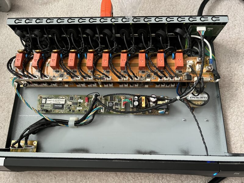
Might as well talk about the inside of the unit, since I opened it to see if there was an obvious problem like a burnt component or a blown capacitor, but the internal 12v PSU seemed to be putting out an acceptable voltage, and there was no obvious issue. It consists of a PSU, a second transformer (unsure of the purpose), the logic board, and two outlet boards. Each outlet has a relay, an LED, and a current sensor (the donuts around the live wire). Neutral and ground are bussed to every outlet. Each control chip controls five outlets.
The logic board connects to the top outlet control board on the left. The top board connects to the bottom board on the right side of the unit, and then the bottom board has a terminator resistor on the left. The logic board also connects to the LED display on the rear of the unit, the serial/feature/LAN ports on the front-left of the unit, and the blue LED on the front-right.
Based on the LAN LED (which also exists on the logic board), it seems to be boot looping. With no LAN cable attached, the LED will illuminate briefly when powering on the unit, and then again after some time. With an Ethernet cable attached, it actually seems to link up, but my switch doesn’t seem to detect any MAC address on that port.
The logic board has unpopulated headers on the back side to directly connect the ethernet/feature/serial ports and a display. I believe this is used for the 0U units.
Moving on…
Second Attempt: DPXR8-15
This time, the factory reset worked fine – poke the reset button, then immediately start pressing Esc on the serial console until you get the => prompt, and then use the defaults command.
Plug it into a network. It will get an IP via DHCP by default. If you don’t see the IP on the prompt on the serial console, press enter to refresh the prompt:

Open it in a browser, and you’ll see an error:

I also couldn’t get SSH to work out of the box – even if I intentionally allowed obsolete ciphers, after entering a username, I never got a password prompt.
I Firefox, you can work around this by setting the about:config property security.tls.version.enable-deprecated to true. You’ll get a warning, but it will be a dismissable warning instead of a hard block.
Interestingly, it seems to use ASP on the backend. I wonder if it’s running some kind of embedded Windows?
When you log in, you’ll be forced to change your password. After that, you should upgrade the firmware. If you have a firmware < 1.5.4, then you need to upgrade to 1.5.4 first before upgrading to anything newer. The firmware upgrade screen is the worst of mid-2000s web design – you click the upload button, and get zero feedback until the upload finishes.
You can also turn off forced HTTPS in Device Settings > Security Settings. It’s probably overall worse for your security to have to enable older TLS versions in your browser. If you plan to use Zabbix or similar to monitor, you’ll also want to use Device Settings > SNMP Settings to enable SNMP. You do not need write access to monitor power.
Inside
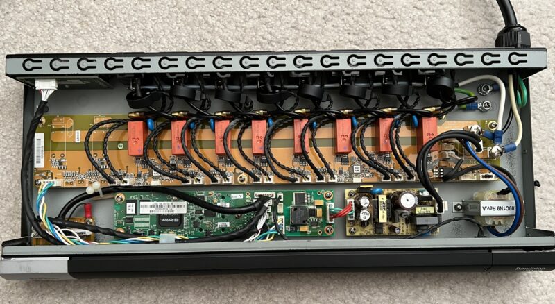
Unsurprisingly, the interior is very similar. This unit appears to have an older PCB based on the sticker which indicates the factory firmware version. It has a single control board, with a terminator on the opposite end, and two unpopulated outlet areas. From what I’ve read on other users reviving dead units, I believe it may be possible to transplant the working logic board into the non-working unit, but it would only be able to control 8 outlets.
Monitoring Power
I found a Zabbix template, but it didn’t work, so I reworked it until it did. Mine measures voltage, current, active power, and apparent power per outlet.
One note is that while the SNMP data has the capability to support multiple poles per inlet, my units are single-input single-pole, and I’m not sure how to do two layers of nested discovery in Zabbix. Poles seem to be PDU-MIB::inletPole<property>.<inletIndex>.<poleIndex>.
Here is my version of the template.
The Data
Here’s what I found from my racks:
- My CRS326-24S-2Q+ is pretty efficient. Even with transceivers, it was only pulling about 20W. Oddly, it seems that rather than the redundant PSUs running active-active, the second PSU draws 0W until the primary PSU has a problem.
- My router host uses about 43W. RAPL reports about 13W of CPU power draw, and 10W of DIMMs. Since the CPU measurement is called
intel-rapl:0and the DIMM measurement isintel-rapl:0:0, I believe that the 10W is included in the 13W, but I’m not sure about this. This means that the rest of the system is only using either 20W or 30W, including an X550-T2 NIC, M.2 drive, fans, and power supply losses. - The CRS328-24P-4S+ uses about 60W, but 30W of that is immediately attributable to PoE devices. Not the worst, but not great either – it means I’m spending 30W but only using 13 gigabit and two SFP+ links.
- Small power adapters (<30W) seem to not bother with power factor correction – they often have 50-70% power factors.
- pve1 (X11SDV-16C-based box) uses about 230W, but that’s more due to all of the other stuff in it. I will see about moving workloads around such that I do not need a SAS expander in that machine.
- pve2 (X11SRM-VF that I talked about in the previous post on this topic) averages 105W. Still doing pretty good on that front. I could get the power draw even lower if I used a simple NVMe boot disk instead of mirrored SAS SSDs – I was using what I had.
- The X-Fi XB8 cable modem/gateway uses about 20W of active power. I am only using it in bridge mode, so none of the WiFi nor MoCA hardware should be active.
I was really hoping for a better “smoking gun”, but there doesn’t seem to be an obvious stinker here. The 230W load isn’t terrible, considering it is home to two 3.84TB NVMe drives, nine hard drives, six other SSDs, a SAS HBA, and a SAS expander.