Installing OpenWRT on a Firebox X550e
I recently came into possession of a Firebox X550e Core that was thrown out due to a bad power supply. Turns out OpenWRT (or almost any OS for that matter) is pretty easy to install on this thing. Read on for some photos and a how-to.
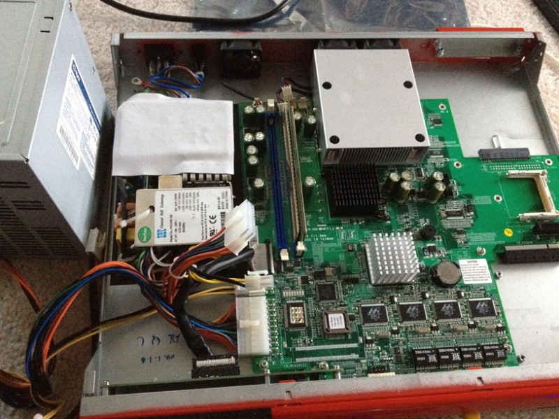
First issue: The dead power supply. Turns out it uses a standard 20-pin ATX power connector and a 4-pin CPU power connector, so almost any PC power supply can run it.
Second issue: Installing an OS.
Requirements:
- Linux box with a serial port
- Null-modem serial cable
- CF card reader
- A partition management program (such as Gparted)
- A program for communicating over a serial port (such as Screen)
The process is fairly simple. Hell, the default firmware even uses GRUB and it has it’s own partition, so I didn’t even have to install a bootloader.
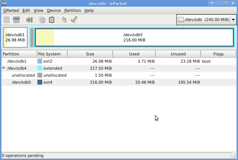
The CF card has 6 partitions by default. We only need a boot partition and a root partition. Open up Gparted or another partition editor and delete everything except the first partition, since it’s where the GRUB is installed. Then, make an EXT4 partition over the rest of the drive (I created it within the extended partition that was already on the card):
Then head over to the appropriate OpenWRT downloads directory and grab “openwrt-x86-generic-rootfs.tar.gz” and “openwrt-x86-generic-vmlinuz”. Extract the rootfs onto your data partition on the CF card, and place the kernel on the boot partition. Next, fire up an editor and edit the /grub/menu.lst on the boot partition. It should end up something like this:
serial --unit=0 --speed=115200 --word=8 --parity=no --stop=1
terminal --silent --timeout=1 serial console
default=0
timeout=5

title OpenWRT
   root (hd0,0)
   kernel /openwrt-x86-generic-vmlinuz rw root=/dev/sda5 console=ttyS0,115200 libata.dma=0
Replace the “5” in “sda5” with whatever partition number your data partition has. However, keep it as “sda” since it will be the first storage device on the firebox. Now, go to the x86 packages directory and download the kmod-skge package, which provides support for the onboard ethernet. Stick this package somewhere on the data partition.
Now, connect a serial cable to the Firebox and your PC. Use “screen /dev/ttyS0 115200” to communicate over the port (press ^A k y to end the session, or ^A d to detach so you can later reattach by using “screen -r”). Unmount, sync, and eject the CF card. Slide it back into the Firebox’s CF slot and power it on. After a while, you should see GRUB come up over the serial console. Let the system continue to boot. It will hang a couple times for up to 30 seconds a couple times during boot (I suspect this is due to a slow card since the drive activity light is solid during these hangs) (this is solved by adding a kernel option to the bootloader, I have edited the post to reflect this) but eventually it will tell you to press enter to activate the console (pay attention, as you may miss it due to other messages appearing after it). Note that this is not the same as the message about pressing f to enter failsafe mode. The normal OpenWRT console should come up.
First, you should probably set a password using “passwd”. Then, use “opkg install <file>” to install the kmod-skge package you downloaded earlier. Once this is installed, ethernet should start working. However, it is likely not configured correctly. If you know what configuration you’d like to use, go ahead and configure it. The below /etc/config/network allows it to act as a simple node on a 192.168/16 network with a static IP:
config interface 'loopback'
   option ifname 'lo'
   option proto 'static'
   option ipaddr '127.0.0.1'
   option netmask '255.0.0.0'

config interface 'lan'
   option ifname 'eth0'
   option proto 'static'
   option ipaddr '192.168.1.9'
   option netmask '255.255.0.0'
   option gateway '192.168.1.1'
   option dns '192.168.1.1'
You should also configure /etc/config/dhcp so that the “lan” section looks like this so that it doesn’t start trying to answer DHCP requests:
config dhcp 'lan'
   option interface 'lan'
   option ignore '1'
Lastly, you will most like want to “rm /etc/resolv.conf” and then “ln -s /tmp/resolv.conf.auto /etc/resolv.conf”. This causes the system to directly use the DNS servers provided by your network config (or by DHCP if you’re using it), rather than trying to do everything through it’s own DNS server. Issue a “/etc/init.d/networking restart” after you’ve done your network configuration. Try pinging things to verify your connectivity. If everything works, you can start configuring it over the network rather than over the serial cable, and start using it as a normal OpenWRT device.
Firebox Details and Photos
Lspci:
00:00.0 Host bridge: Intel Corporation Mobile 915GM/PM/GMS/910GML Express Processor to DRAM Controller (rev 04)
00:02.0 VGA compatible controller: Intel Corporation Mobile 915GM/GMS/910GML Express Graphics Controller (rev 04)
00:1d.0 USB controller: Intel Corporation 82801FB/FBM/FR/FW/FRW (ICH6 Family) USB UHCI #1 (rev 04)
00:1d.1 USB controller: Intel Corporation 82801FB/FBM/FR/FW/FRW (ICH6 Family) USB UHCI #2 (rev 04)
00:1d.2 USB controller: Intel Corporation 82801FB/FBM/FR/FW/FRW (ICH6 Family) USB UHCI #3 (rev 04)
00:1d.3 USB controller: Intel Corporation 82801FB/FBM/FR/FW/FRW (ICH6 Family) USB UHCI #4 (rev 04)
00:1d.7 USB controller: Intel Corporation 82801FB/FBM/FR/FW/FRW (ICH6 Family) USB2 EHCI Controller (rev 04)
00:1e.0 PCI bridge: Intel Corporation 82801 Mobile PCI Bridge (rev d4)
00:1f.0 ISA bridge: Intel Corporation 82801FBM (ICH6M) LPC Interface Bridge (rev 04)
00:1f.1 IDE interface: Intel Corporation 82801FB/FBM/FR/FW/FRW (ICH6 Family) IDE Controller (rev 04)
00:1f.3 SMBus: Intel Corporation 82801FB/FBM/FR/FW/FRW (ICH6 Family) SMBus Controller (rev 04)
01:00.0 Ethernet controller: Marvell Technology Group Ltd. 88E8001 Gigabit Ethernet Controller (rev 13)
01:01.0 Ethernet controller: Marvell Technology Group Ltd. 88E8001 Gigabit Ethernet Controller (rev 13)
01:02.0 Ethernet controller: Marvell Technology Group Ltd. 88E8001 Gigabit Ethernet Controller (rev 13)
01:03.0 Ethernet controller: Marvell Technology Group Ltd. 88E8001 Gigabit Ethernet Controller (rev 13)
01:04.0 Network and computing encryption device: Cavium Networks Nitrox XL N1 Lite
cpuinfo:
processor       : 0
vendor_id       : GenuineIntel
cpu family      : 6
model           : 9
model name      : Intel(R) Celeron(R) M processor         1300MHz
stepping        : 5
microcode       : 0x45
cpu MHz         : 1299.969
cache size      : 512 KB
fdiv_bug        : no
hlt_bug         : no
f00f_bug        : no
coma_bug        : no
fpu             : yes
fpu_exception   : yes
cpuid level     : 2
wp              : yes
flags           : fpu vme de pse tsc msr mce cx8 apic sep mtrr pge mca cmov clflush dts acpi mmx fxsr sse sse2 tm pbe bts
bogomips        : 2599.93
clflush size    : 64
cache_alignment : 64
address sizes   : 32 bits physical, 32 bits virtual
power management:
Expansion:
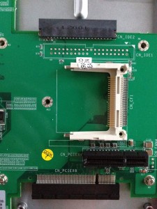
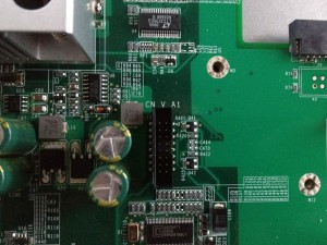
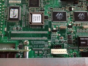
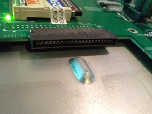
The firebox has 2 DDR2 slots, but I can’t get it to see anything over 1GB of RAM. As for ports, it has a keyboard and mouse ports (one of them seems to be a PS/2 port, not sure what the other is). It has a port labeled “CN V A1” which I have no idea about. It has solder pads for a mini-PCI slot, a PATA port, 2 USB ports, and another serial port. There appears to be some kind of PATA connector on the motherboard although it doesn’t look like any of the normal IDE connectors. Its has a CF slot, a PCIe x4, and a PCIe x8. There’s also a JTAG connector, a clear CMOS jumper, and a couple blocks of DIP switches.

September 15th, 2013 at 14:06
Matt,
You stated that it would be easy to install almost any OS. So I could install Linux on an old X550e and use it as a server?
Jeff
October 31st, 2014 at 21:31
[…] started using the Firebox mentioned previously as my main device. I upgraded it to 14.07 and had to go through the installation process again, so […]
November 30th, 2014 at 01:21
ZQuiet Review
Matt Ventura’s blog » Blog Archive » Installing OpenWRT on a Firebox X550e
May 4th, 2017 at 10:47
Hi,
I suspect that the “CN V A1” is for VGA (“connector video analog 1”), but it’d need an oscilloscope to verify that and check the pinout.
If you take the front panel off, a USB port will reveal itself! (after a little case mod it could be used for a LTE modem, additional storage, printer etc.).
X550e was the lowest model on these series, the higher-end X750e and X1250e had more parts installed, but the motherboard seems the same.
See the thing on http://www.lnx.ro/2015/01/09/pfsense-on-a-watchguard-firebox/
The PCI-e x8 was used for an additional 4x1000BASE-T NIC in X750e and X1250e. PCIEx4 was meant for some kind of an expansion card (not standard PCIe) inserted into the upper slot on the back panel.
The small IDE connector accepted 2.5″ HDDs with an adapter (you can sometimes see that on old laptops) slid into the lower slot on X1250e and maybe even X750e.
I wonder if both IDE sockets are connected in parallel, so you could use a hot-air station to solder a normal IDE in and drop an old HDD into the box.
May 25th, 2017 at 21:58
I was considering looking further into the HDD ports, but because I couldn’t get DMA to work on the CF slot I figured it might not have worked on the proper HDD slots either.
December 8th, 2017 at 03:48
Hi all,
Found this link which contains details of a cable and of the pin out for the CN_V_A1.
I googled 16pin VGA and looked at the image search.
The image is – https://www2.warwick.ac.uk/fac/sci/csc/people/computingstaff/jaroslaw_zachwieja/readynaspro-jailfix/15-vga-16-pin.jpg
The page with details is – https://warwick.ac.uk/fac/sci/csc/people/computingstaff/jaroslaw_zachwieja/readynaspro-jailfix/
That page refers to a website with further technical details and where American’s can purchase the cable – https://www.pccables.com/VGA_PORT_HD15F_PORT_To_IDC16.htm
I’m going to look at my collection of old graphics cards in the loft for the cable, but the provided pin out will mean I can mash something together if I find nothing.
Thought it might be helpful.
Regards,
MATT (shotgun25)
December 8th, 2017 at 09:50
Hi again,
For anyone interested I found a PDF for the VGA and other pinouts across various models here http://www.sechsender.com/bilder/forum/WG_pfsense_guide.pdf
WG Description VGA female
1 Red 1
2 n.c. n.c.
3 Green 2
4 GND? n.c.
5 Blue 3
6 n.c. n.c.
7 n.c. n.c.
8 V_SDAT 12
9 GND 5
10 Hsync 13
11 GND 6
12 Vsync 14
13 GND 7
14 V_SCLK 15
15 GND 8
16 n.c. n.c.
I’ve just finished verifying this with a cut in half VGA cable and an adaptor from the front case cabling from an old computer case (2x USB (10 wires) + LED wiring (8 wires)) that had a perfect fit plastic end.
Hope it helps
Regards,
MATT (shotgun25)
November 6th, 2024 at 03:26
### Notes on Following the Tutorial in 2024
#### OpenWrt 12.09 (version used in the tutorial)
– Use EXT3 instead of EXT4 for the root filesystem, since the older EXT4 driver in the 2013 kernel doesn’t support newer EXT4 partitions.
#### OpenWrt 23.05 (most recent version as of 2024-11)
– Since the newer kernel is considerably larger, the boot partition needs to be expanded, and the kernel path in `/grub/menu.lst` must be adjusted.
Current Download Links (2024):
– Supported CPU architecture for Firebox x550e is [x86-legacy](https://downloads.openwrt.org/releases/23.05.5/targets/x86/legacy/)
– RootFS Download: https://downloads.openwrt.org/releases/23.05.5/targets/x86/legacy/openwrt-23.05.5-x86-legacy-rootfs.tar.gz
– Kernel Download: https://downloads.openwrt.org/releases/23.05.5/targets/x86/legacy/openwrt-23.05.5-x86-legacy-generic-kernel.bin
– Ethernet Kernel Module: https://downloads.openwrt.org/releases/23.05.5/targets/x86/legacy/kmods/5.15.167-1-a533a9c4d5c3539aac3572d665c91e88/kmod-skge_5.15.167-1_i386_pentium-mmx.ipk